Physical Installation
Overview
This guide describes the procedures for installing, cabling, and provisioning Lantronix Local Managers.
This guide applies to the following models:
- Lantronix LM83X
- Lantronix LM80
Please read the Lantronix Safety Summary before proceeding with installation.
Site Requirements
Ensure that the power source meets the following requirements:
- Provides appropriate power (AC or DC) as required by the Local Manager
- Provides overload protection
- Is connected to earth ground
Ensure the installation site ambient temperature does not exceed 113F (45C) or fall below 32F (0C).
Optional equipment
The following optional equipment is available for Lantronix Local Managers.
- v.92 modem
- DB-9 (RS-232) serial module
- Cellular modem
- SFP (fiber) module
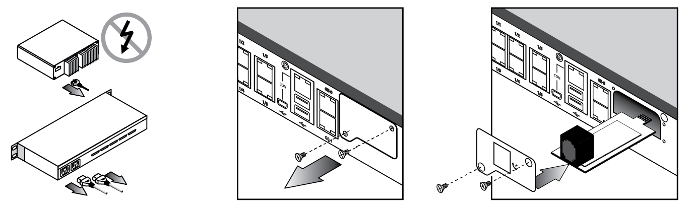
Install a v.92 modem
Follow these steps if a v.92 modem is not already installed in the option slot.
- Power off the Local Manager.
- Remove the option slot cover, align the modem carrier card with the internal rails, and slide the modem into place.
- Replace the screws.
- Connect a POTS telephone line to the RJ-11 jack on the modem
- Power on the Local Manager.
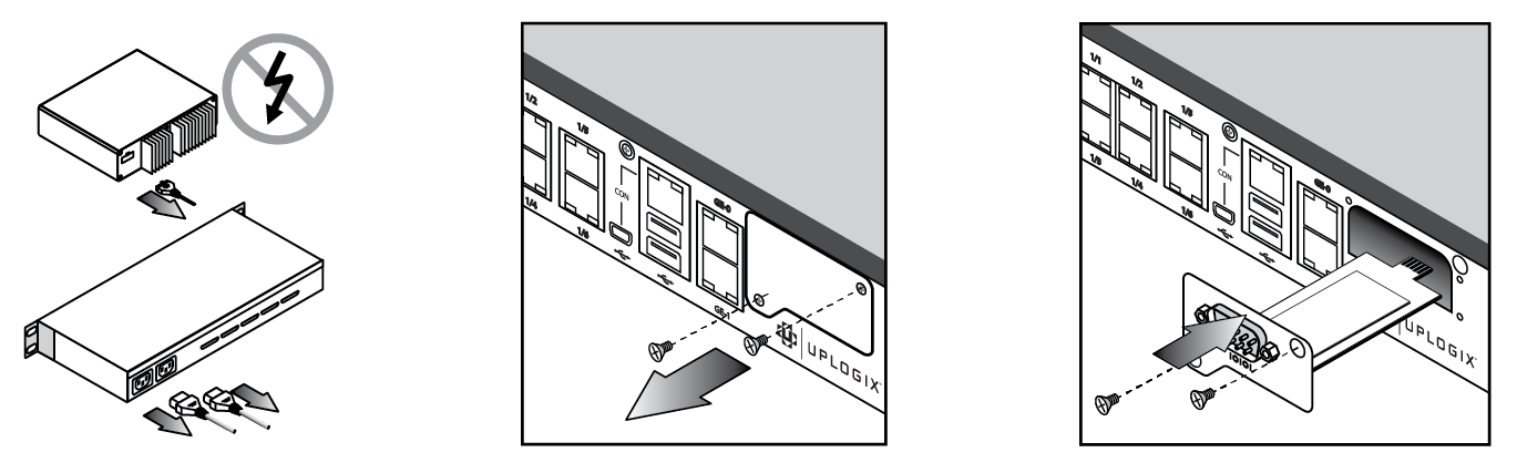
Install a DB-9 serial module
The DB-9 serial module is used in the following scenarios:
- External v.92 modem
- External standalone Iridium (9522B)
- Lantronix LEO-I Kit
- External cellular modems
Follow these steps if a DB-9 serial module is not already installed in the option slot.
- Power off the Local Manager.
- Remove the option slot cover, align the DB-9 card with the internal rails, and slide the card into place.
- Replace the screws.
- Power on the Local Manager.
Install a GPRS cellular modem
Follow these steps to install the GPRS cellular modem:
- Power off the Local Manager.
- Install an activated SIM card on the modem.
- Remove the option slot cover, align the modem carrier card with the internal rails, and slide the modem into place.
- Feed wire into the option slot compartment, align modem cover plate with the option slot screw holes, and replace the screws.
- Install antenna.
- Power on the Local Manager.
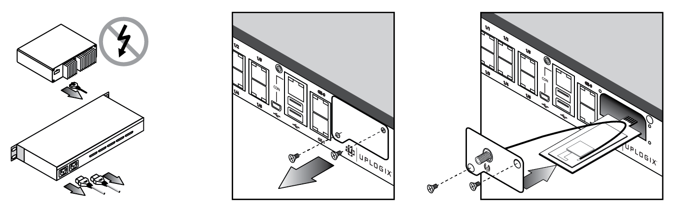
Install a CDMA cellular modem
Follow these steps to install the CDMA cellular modem:
- Power off the Local Manager.
- Note the Electronic Serial Number (ESN) on the modem, as this will be needed in order to activate the modem on your carrier's network.
- Remove the option slot cover, align the modem carrier card with the internal rails, and slide the modem into place.
- Feed wire into the option slot compartment, align modem cover plate with the option slot screw holes, and replace the screws.
- Install antenna.
- Power on the Local Manager.
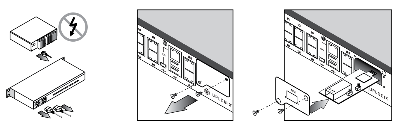
Install an SFP module
Follow these steps to install the SFP module:
- Power off the Local Manager
- Remove the option slot cover, align the carrier card with the internal rails, and slide the module into place.
- Replace the screws.
- Install either a 1000Base SX (GLC-SX-MM) SFP or the 1000Base LX/LH (GLC-LH-SM) SFP for fiber connectivity. Both the 1000Base SX (GLC-SX-MM) SFP and the 1000Base LX/LH (GLC-LH-SM) SFP are customer-provided equipment.
Install a temperature and humidity sensor
Environmental monitoring is available via a USB-connected temperature and humidity sensor.
Follow these steps to connect the sensor. Note the Local Manager does not need to be powered down for installation of this sensor.
- Plug the sensor into one of the two USB connections on the Local Manager.
- Place sensor collection end in the area you wish to collect environmental information, ideally not near a fan or on hot equipment.
It may take up to 10 minutes for the sensor to normalize to the environmental temperature and begin reporting consistent data.
Install expansion cards
Please see the following documents for more information about expansion cards:
Use the following procedure to install or replace an expansion card.
-
Power off the Local Manager.
-
Using a #2 Philips screwdriver, loosen the module screws securing the blank faceplate or the option card to be replaced and remove it.
-
Slide the new or replacement option card into place. Ensure the two module retention screws are threaded into the faceplate of the card. The screws will align to holes in the chassis if the screws are slightly backed out of the front panel.
Installing the option card with the screws fully engaged makes it difficult to install the card properly. -
Look inside the chassis and find two tabs close to the front of the option slot and two located further back. Place the rear edge of the card on the two front tabs, tilt the card up and slide it back so the card edges slide below the two rear tabs. Gently push the card back until the card seats in the connector on the backplane.
If it is difficult to slide the card or if the card resists being properly seated, the card is probably not installed correctly. Remove the card and start over. Very little force is required to install the cards. -
Tighten the module retention screws to ensure that the internal connector seats properly.
Over tightening the screws may strip the threads and is not required; finger tight is sufficient. As you install the retention screws, you may encounter some resistance. If needed, use a #2 Philips screwdriver to overcome this resistance but use care not to cross thread or strip the screw. -
If you are installing a 16 port serial card, attach the supplied octopus cable to the connector on the front of the card.
Install chassis in rack
Lantronix Local Managers are designed for standard 19-inch telco racks.
The Lantronix 500 ships with rubber standoffs for desktop use.
Lantronix LM83X
To mount the Local Manager in a rack:
- Use the included screws to attach the mounting brackets.
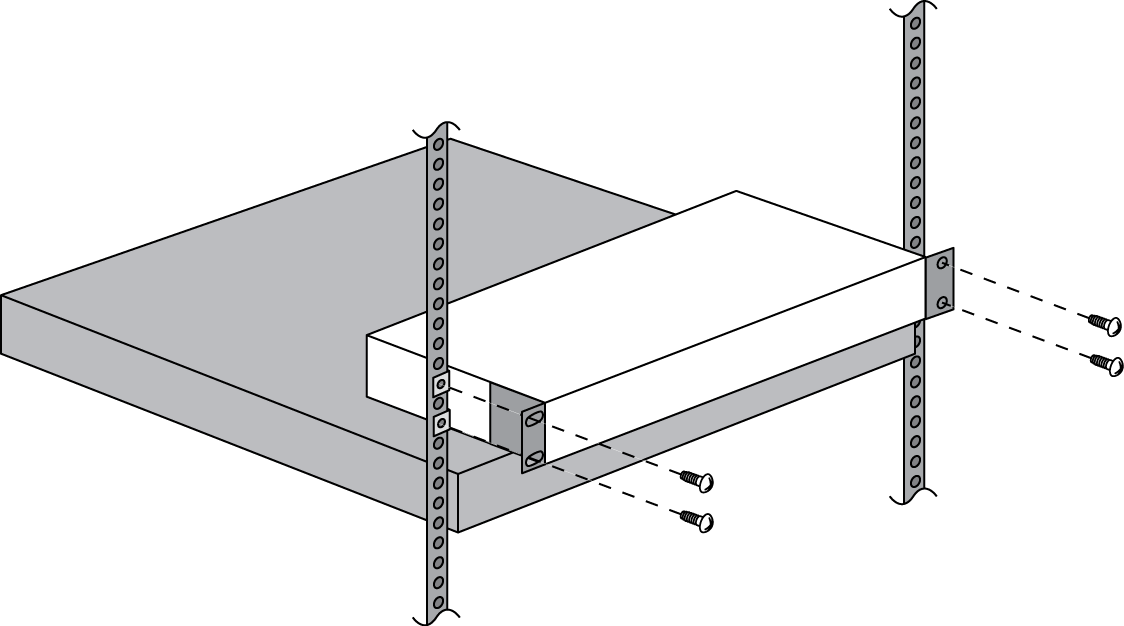
- Mount the Local Manager in the rack
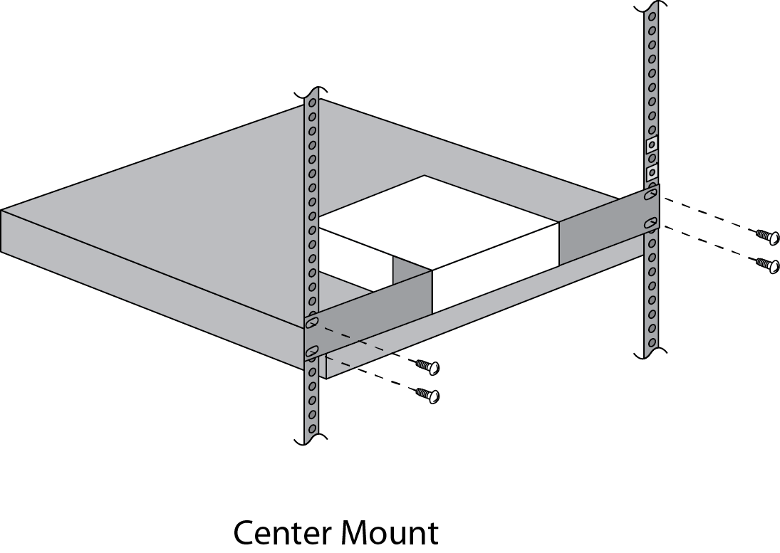
Lantronix LM80
To mount the Local Manager with the optional center-mount kit:
- Attach the mounting brackets.
- Mount the Local Manager in the rack.
Connect to power
Before connecting the Local Manager to power, ensure all site requirements are met.
Connect the power cord to the Local Manager. Use either the provided power cord or one that is suitable for your location. The Lantronix Local Manager uses a power cord with a standard IEC-320-C13 female cord end.

Connect the power cord to a power outlet. A dimly lit keypad and dark display (if installed) indicates that the unit has power applied. Power the unit on by pressing the middle keypad button. The display on the front panel will illuminate and display progress messages as the device boots. At the end of the boot sequence, it displays the message Lantronix status good.
Installation complete
You are now ready to complete the initial setup of the Lantronix Local Manager.